
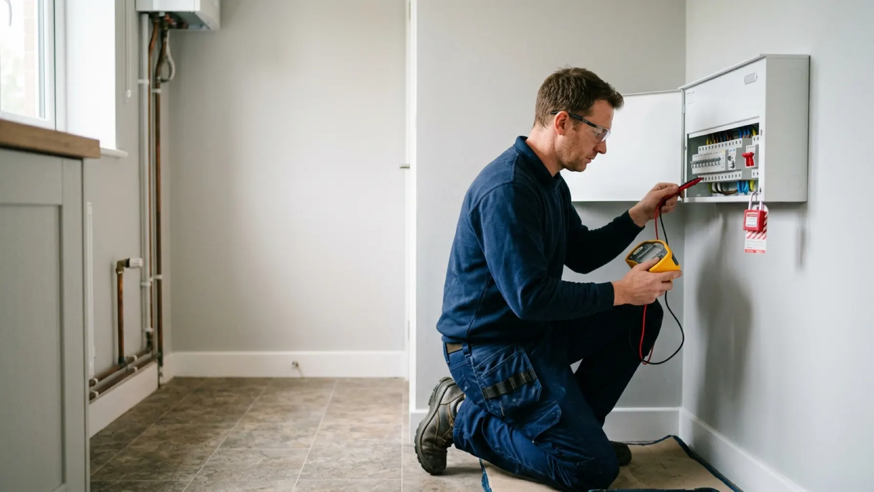
What initial verification is for
Initial verification is the process of confirming that a new installation, or an addition or alteration to an existing one, complies with BS 7671 before it is put into service. It is not a formality at the end of the job — it is the point at which someone competent takes responsibility for saying the installation is safe to energise.
It has three parts, and they happen in this order:
- Inspection — carried out, so far as is reasonably practicable, with the installation disconnected.
- Testing — the dead tests first, then the live tests once the installation has been safely energised.
- Certification — recording what was found on an Electrical Installation Certificate with its accompanying schedules.
Skipping or reordering these is one of the most reliably examined mistakes in the 2391-52. Inspection comes before testing because a visual defect that testing would not reveal — a missing barrier, an unsuitable enclosure — should be found before anything is energised.
Information required before you start
Regulation 641.2 requires that the person carrying out the verification is provided with the design information for the installation. In practice, that means you cannot properly verify what you have no description of. You should have:
- the design criteria and any assessment of general characteristics
- the earthing arrangement (TN-S, TN-C-S, TT and so on) and the supply characteristics
- circuit details: conductor sizes, protective device types and ratings, and the reference method used
- the maximum demand and any diversity applied
- any departures from BS 7671, with the reasoning for them
Where that information is missing, that is itself a finding. You cannot certify an installation as compliant with a design you have never seen.
The Schedule of Inspection
The inspection covers everything the eye and the hand can confirm. The app’s Visual Inspection checklist follows the same ten groupings used on a Schedule of Inspection:
| Group | Typical checks |
|---|---|
| Consumer unit / distribution board | Enclosure condition, non-combustible construction (Reg 421.1.201), circuit labelling (Reg 514.9.1), accessible main switch (Reg 537.1.4), SPD where required (Reg 443.4.1) |
| Protective devices | Correct type and rating, RCD protection where required (Reg 411.3.3), coordination (Reg 536.1) |
| Cables and conductors | Correct sizing, support, protection against mechanical damage, correct identification |
| Wiring systems | Suitability for the location and installation method |
| Earthing and bonding | Main protective bonding, earthing conductor, presence and continuity of CPCs |
| Isolation and switching | Devices for isolation, switching off for mechanical maintenance and emergency switching |
| Protection against fire | Fire barriers, sealing of penetrations, correct enclosure materials |
| Accessories and equipment | Condition, suitability, correct connection |
| Special locations | The additional requirements of Part 7 where they apply |
| Documentation and notices | Warning and identification notices, diagrams and charts |
Items that bear directly on safety — the earthing arrangement, RCD provision, the non-combustible enclosure requirement — carry more weight than cosmetic ones, and are the ones the exam tends to build questions around.
The test sequence
The order of tests is set by Regulation 643.1, and it is deliberate. Each test either depends on the one before it or would be dangerous without it.
Dead tests, before energising
- Continuity of protective conductors (Reg 643.2) — including main and supplementary bonding, and the R1+R2 of each circuit.
- Continuity of ring final circuit conductors — the three-step figure-of-eight method.
- Insulation resistance (Reg 643.3) — to the test voltages and minimum values in Table 64.
- Protection by SELV, PELV or electrical separation (Reg 643.4), where those measures are used.
- Polarity (Reg 643.6) — confirmed dead, before there is any chance of energising a reversed circuit.
Live tests, after safe energising
- Earth fault loop impedance (Reg 643.7)
- Prospective fault current (Reg 643.7.3.201)
- RCD operation (Reg 643.8)
- Phase sequence, on polyphase circuits (Reg 643.9)
- Functional testing (Reg 643.10)
Polarity is tested dead and then confirmed again live. A polarity fault found after energising has already had the opportunity to do damage — which is exactly why the dead test comes first.
Insulation resistance values
| Circuit nominal voltage | Test voltage (DC) | Minimum insulation resistance |
|---|---|---|
| SELV and PELV | 250 V | 0.5 MΩ |
| Up to and including 500 V | 500 V | 1.0 MΩ |
| Above 500 V | 1000 V | 1.0 MΩ |
BS 7671 Table 64 / Reg 643.3.2.
A common exam trap is to pair the SELV test voltage with the low-voltage minimum resistance, or the other way round. Learn the rows as pairs, not as four separate numbers.
Certification
Initial verification is certified on an Electrical Installation Certificate (Reg 644.1), which must be accompanied by a Schedule of Inspections and a Schedule of Test Results. The EIC carries three signatures — for design, for construction, and for inspection and testing — which may be one person or three, depending on who did what.
Where the work is an addition or alteration to an existing circuit that does not include a new circuit or the replacement of a distribution board or consumer unit, a Minor Electrical Installation Works Certificate (Reg 644.4.201) is the correct document instead. Choosing between them is covered in more depth under certification and reporting.
Where candidates lose marks
- Giving the test sequence in the wrong order, particularly putting polarity before insulation resistance.
- Treating initial verification and periodic inspection as the same activity. They are not: one confirms compliance before service, the other assesses condition in service.
- Forgetting that the design information is a prerequisite, not an optional extra.
- Reciting Table 64 values without being able to say which test voltage goes with which minimum.